Guides / Finishes
PVD Deposition Methods: Cathodic Arc vs Sputtering vs HiPIMS
October 18, 2026
Cathodic arc vs magnetron sputtering comes down to ionization against smoothness. A cathodic arc turns the target into a highly ionized metal plasma that gives dense, well-bonded coatings at a high rate, but it also throws out molten droplets that roughen the surface. Magnetron sputtering gives smooth, droplet-free films at a lower rate and lower ion energy. HiPIMS is a pulsed form of sputtering that adds much of the arc’s ionization without the droplets. Values in this guide are typical, not promised.
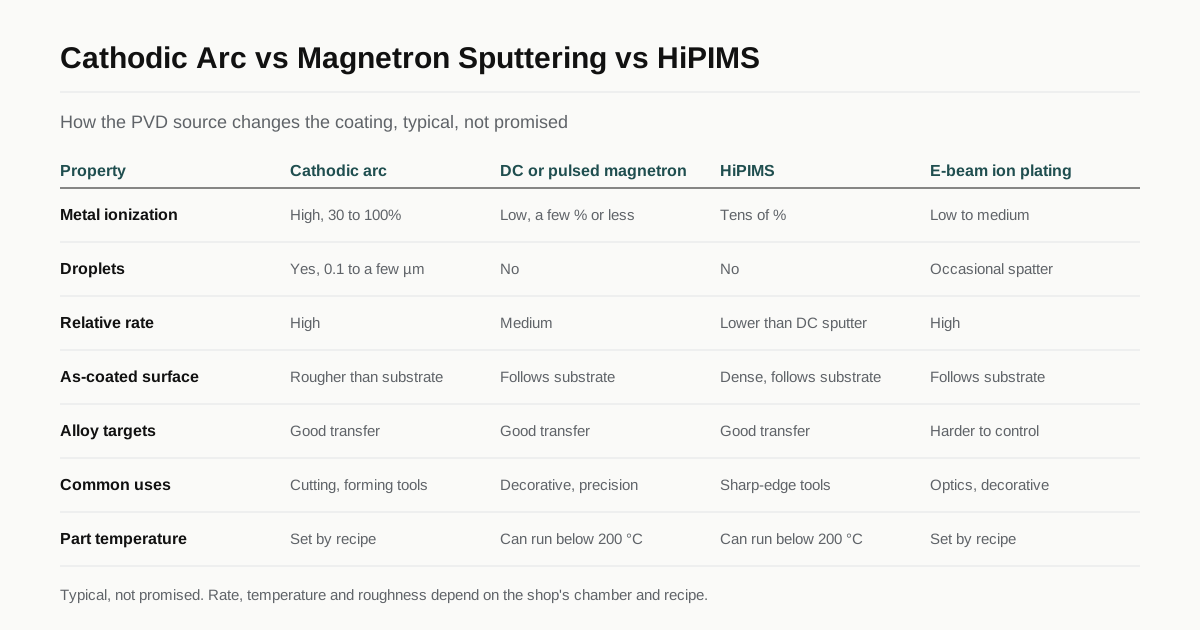
This guide goes one level below the PVD overview. It explains how each source makes its vapor, what that does to the coated part and how rotation, bias and etching in the chamber shape the result.
What every PVD cycle has in common
Every PVD process runs the same basic cycle, whatever the source:
- Load and pump down to a base pressure commonly around 10⁻⁵ mbar or lower.
- Heat. Radiant heaters drive moisture and trapped gas off parts and fixtures.
- Etch. Argon or metal ions bombard the parts to remove oxide and contamination.
- Deposit. The source makes metal vapor. Nitrogen gives nitrides, acetylene or methane gives carbonitrides and carbon films. Working pressure sits roughly between 0.1 and a few pascal.
- Cool and vent. The load cools under vacuum before the door opens.
Door to door this often takes several hours. What separates the source types is how they make the vapor and how much of it is ionized.
Ionization matters because only ions respond to the negative bias on the parts. More ions means more energy delivered to the growing film, which gives density, adhesion and compressive stress. Too much gives brittle films that flake at sharp edges.
Unfamiliar terms are defined in the PVD coating glossary, and the buying path is in our guide to PVD coating services.
Cathodic arc evaporation
A cathodic arc runs a low-voltage, high-current discharge across the target. The current concentrates in fast-moving cathode spots a few micrometers wide, each of which melts a tiny volume and turns it into plasma. The vapor leaving the target is highly ionized: the Wikipedia article on cathodic arc deposition gives ionization in the range of 30 to 100 percent depending on the material. Many ions are multiply charged, with energies of tens of electronvolts.
Strengths. High deposition rate. Dense films. Very good adhesion, because the same source can run a metal-ion etch at high bias before deposition. Alloy targets such as TiAl and AlCr transfer their composition to the film fairly well, which is why arc is the common production route for TiAlN, AlTiN and AlCrN on cutting tools. See types of PVD coating for what those chemistries do.
Weakness: macroparticles. The arc spot also ejects molten droplets of target material, commonly 0.1 to a few µm across and occasionally larger. Targets rich in low-melting aluminum tend to produce more of them. The coating grows over each droplet as a nodule. Some nodules break out in service or during polishing and leave a pinhole down to the substrate.
Shops reduce droplets in three ways:
- Steered arc. Magnets behind the target move the spot faster and shrink the droplets.
- Filtered arc. A curved magnetic duct guides ions to the parts while droplets hit the duct wall. It costs much of the rate and is the usual route for hydrogen-free ta-C.
- Post-coat finishing. Drag finishing, brushing or microblasting knocks off the nodule tops.
What droplets mean for your part
On drills and end mills droplets matter little, though many tool makers polish flutes after coating so chips flow. On forming punches and dies nodules pick up sheet material, so a post-coat polish is common. On a mirror-polished decorative part or a precision sealing face, the droplets can be the deciding defect. In those cases ask for a sputtered, HiPIMS or filtered arc process. You can also put a maximum Ra after coating on the drawing.
Magnetron sputtering
In magnetron sputtering, magnets behind the target trap electrons near its surface and keep a dense argon plasma there. Argon ions hit the target and knock atoms off it. The flux leaving the target is mostly neutral atoms with a few electronvolts of energy. The ionized share of the metal is low, commonly a few percent or less.
Unbalanced and closed-field magnetrons let part of the plasma reach the load and raise the ion current at the substrate. Pulsed DC power, commonly tens to hundreds of kHz, suppresses arcing in reactive mode.
Reactive sputtering has one control problem the buyer sees indirectly. As nitrogen flow rises, the target surface turns to nitride (target poisoning) and the rate drops sharply. Shops run closed-loop control on optical emission or gas partial pressure to hold the process in the transition zone. That control is much of what keeps decorative TiN or ZrN color consistent between batches.
Strengths. Smooth, droplet-free films that follow the substrate finish. Process temperature can be held below 200 °C. Almost any conductive target works. RF power can sputter insulators. Sputtering is the usual route for WC/C carbon films, TiB₂ for aluminum cutting and many decorative and precision coatings.
Weakness. Lower rate than arc and lower ion flux. Without enough bias and ion assist, sputtered nitrides can grow with an open columnar structure. Adhesion leans more on the etch step and the metal bond layer.
HiPIMS
HiPIMS, high power impulse magnetron sputtering, uses the same magnetron hardware but delivers the power in short, very intense pulses. The Wikipedia article on HiPIMS describes peak power densities of several kW/cm² in pulses of tens of microseconds at duty cycles below 10 percent. The plasma in each pulse is dense enough to ionize a large share of the sputtered metal, tens of percent depending on the material.
Strengths. Dense, smooth films with no droplets. Bias can steer the ions, which helps coverage on edges. A HiPIMS metal-ion etch gives arc-like adhesion without arc droplets at the interface.
Weakness. Rate. Part of the ionized metal is pulled back to the target, so deposition is lower than DC sputtering at the same average power. Fewer shops run HiPIMS in production, which limits the choice of suppliers. It suits sharp micro tools, smooth forming tools and precision components where a droplet would be a defect.
Evaporation and ion plating
Thermal and electron-beam evaporation heat the source until it boils off. Plain evaporation has low particle energy and serves optical layers and aluminum metallizing of plastics, not wear coatings.
Ion plating adds a plasma, often from a low-voltage electron beam or hollow cathode, that ionizes part of the vapor, plus a bias on the parts. It was one of the first industrial routes for TiN on tools and some lines still run it. Rates are high and films are smooth. Alloy composition is harder to control because elements evaporate at different rates, which is one reason multi-element nitrides such as AlTiN are mostly made by arc or sputtering.
Some shops call any biased PVD process “ion plating”. Ask which source the shop runs.
Typical values by method
| Cathodic arc | DC or pulsed magnetron | HiPIMS | E-beam ion plating | |
|---|---|---|---|---|
| Metal ionization | High, often 30 to 100% | Low, a few % or less | Tens of %, material dependent | Low to medium |
| Droplets | Yes, 0.1 to a few µm | No | No | Occasional spatter |
| Relative rate | High | Medium | Lower than DC sputtering | High |
| As-coated surface | Rougher than substrate | Follows substrate | Follows substrate, dense | Follows substrate |
| Alloy targets | Good transfer | Good transfer | Good transfer | Harder to control |
| Common uses | Cutting and forming tools | Decorative, precision, carbon films, low temperature | Sharp-edge tools, precision parts | Optics, decorative, some tool lines |
Rate and roughness depend on the shop’s recipe as much as on the source. Treat the table as a ranking, not as drawing data.
Process temperature is set by the recipe
The source type changes how much heat reaches the parts. Arc and HiPIMS deliver more ion energy, which heats the load. Still, the shop sets the part temperature mainly through the heaters, the bias and the cycle length. Tool coatings on carbide and high speed steel commonly run around 400 to 500 °C. Sputtered and HiPIMS recipes for tempered steels, decorative parts and carbon films can run below 200 °C.
A steel part tempered below the coating temperature loses hardness. Ask whether the shop’s figure comes from a thermocouple on a dummy part or from the heater setpoint, since the two can differ. The PVD temperature and substrates guide lists common steels and their limits.
Chamber loading, rotation and bias
Rotation
Parts sit on spindles or satellites on a rotating table. Coaters describe this as:
- 1-fold: table rotation only, used for large or flat parts.
- 2-fold: table plus satellites turning on their own axes.
- 3-fold: table, satellites and spindles that also spin each part, common for round tools.
A surface collects coating only while it faces a source. More rotation axes even out thickness on round parts, but every face still gets a different dose. Closely packed parts shade each other. A denser load lowers cost per part but widens the thickness spread. Specify a thickness range such as 2 to 4 µm on the functional face, not a single value.
Holes and recesses
PVD flux travels in straight lines. Many shops work to a rough rule that useful thickness reaches only about one hole diameter into an open bore. Blind holes get less. If a bore must be coated, mark it and ask the shop what thickness it can reach there.
Bias
The parts carry a negative bias, commonly tens to a couple of hundred volts during deposition. Higher bias gives denser, harder films with higher compressive stress, until the film chips at sharp edges. Every part must make good electrical contact with the fixture. Parts should arrive demagnetized, since residual magnetism disturbs the plasma and holds swarf.
Etching before deposition
Adhesion is decided before the first atom of coating arrives. Shops use one or more etches:
- Argon glow discharge etch at a few hundred volts bias, sometimes boosted by a hot filament or auxiliary arc.
- Metal-ion etch from an arc source at high bias, commonly several hundred volts up to around 1000 V. It cleans and implants metal ions for very strong bonding, but leaves some droplets at the interface.
- HiPIMS metal-ion etch, which gives a similar bond without arc droplets.
Adhesion is usually checked with a Rockwell C indentation on a coupon and graded HF1 to HF6 under VDI 3198, with HF1 to HF4 commonly accepted. On cutting tools, edge honing before coating matters as much as the etch.
Which method suits which part
- Cutting tools: drills, end mills, inserts. Arc is the default for TiAlN, AlTiN and AlCrN. HiPIMS or sputtering for sharp micro tools. Sputtered TiB₂ or filtered arc ta-C for aluminum.
- Forming, blanking and stamping tools. Arc with a post-coat polish. Sputtering or HiPIMS where a smooth surface matters more than rate.
- Decorative parts. Both arc and sputtering are used. Mirror finishes favor droplet-free processes. Color consistency depends on reactive gas control.
- Precision components: pumps, valves, fuel system parts, sliding pairs. Sputtered or plasma-assisted carbon films at low temperature, droplet-free.
If you are weighing PVD against hard chrome on hardened steel, electroplated steel over 39 HRC needs a hydrogen embrittlement relief bake under ASTM B850, which PVD does not. See the wear surfaces guide for the alternatives.
Getting PVD quoted
Specify results, not equipment. A useful RFQ for PVD lists:
- Substrate, hardness and tempering temperature.
- Coating type. If you are not sure, the function it must serve.
- Thickness range on the functional faces.
- Surfaces to coat and surfaces to keep free, including bores.
- Ra before coating and the maximum Ra after coating. Say whether post-coat polishing is acceptable.
- Whether droplets are acceptable on any face.
- Batch size, test coupons and the adhesion and thickness report you expect.
The coating RFQ checklist covers the general items. We are a matching service, not a coating shop. Choose “PVD” as the finish on the RFQ form and describe the part. We pass it to up to 3 shops that run the coating and source your part needs, they quote you directly and you get a reply within 24 business hours. Send your PVD RFQ.
Sources
- Cathodic arc deposition, Wikipedia (arc spots, ionization, macroparticles, filtering)
- High-power impulse magnetron sputtering, Wikipedia (pulse power density, duty cycle, ionization)
Frequently asked questions
What is the main difference between cathodic arc and magnetron sputtering?
A cathodic arc evaporates the target through tiny arc spots and produces a highly ionized metal vapor, which gives dense, well-bonded coatings at a high rate but also ejects molten droplets. Magnetron sputtering knocks atoms off the target with argon ions. The vapor is mostly neutral, the rate is lower and the film is smooth and droplet-free.
Why are arc PVD coatings rougher than the part was before coating?
The arc spot throws out small molten droplets of target material, commonly 0.1 to a few µm across. They land on the part and the coating grows over them as nodules. Some fall out later and leave pinholes. On a ground or polished surface this raises Ra and can show as a haze. Tool and die shops often polish, brush or microblast after arc coating.
Is HiPIMS better than arc for cutting tools?
Not in every case. HiPIMS gives dense, droplet-free films with high metal ionization, which suits sharp micro tools and parts that must stay smooth. Its rate is lower than DC sputtering at the same average power and well below arc, so cost per batch can be higher. Arc remains the common route for AlTiN and AlCrN on general carbide tools.
Does the PVD method decide the process temperature?
Only partly. Arc sources heat the parts more through ion bombardment, but the shop sets the part temperature mainly through heaters, bias and cycle length. Sputtering and HiPIMS recipes can run below 200 °C, while tool coating cycles commonly run around 400 to 500 °C. Ask for the measured part temperature rather than the heater setpoint. Compare it with your tempering temperature.
Should I name the deposition method on my drawing?
Usually not. Specify the result you need: coating type, thickness range, Ra after coating, adhesion class, maximum part temperature and coated surfaces. Name a method only when the function depends on it, for example a droplet-free surface on a sealing face. Fixing the method on the drawing can rule out shops that meet the requirement another way.
Need a quote for this finish?
Send the drawing. We match you with up to 3 finishing shops that run your spec and reply within 24 business hours.
Get matched with a coating shop