Guides / Specs
How PVD Coating Adhesion, Thickness and Hardness Are Tested
October 18, 2026
A PVD coating adhesion test is usually the Rockwell C indentation test to VDI 3198, read on a coupon that ran in the same chamber load as your parts. When a number in newtons is needed, the scratch test to ISO 20502 or ASTM C1624 adds critical loads. Thickness is checked by ball crater to ISO 26423 and hardness by nanoindentation to ISO 14577, because a film of 1 to 5 µm is too thin for a normal thickness gauge or a standard Vickers test. Values in this guide are typical, not promised.
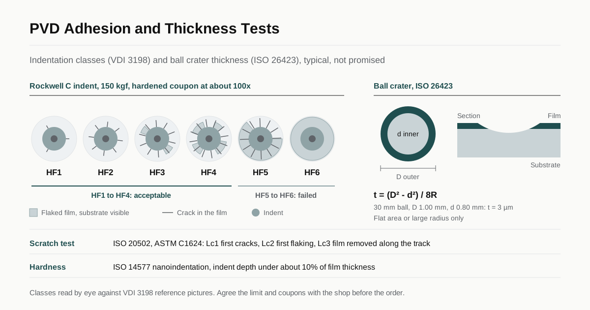
This guide goes one level below our PVD coatings overview: how each test works, what it can miss and what to put on the RFQ.
Why thin hard films need their own tests
Plating QC tools do not transfer well to PVD. Three reasons stand out.
- Thickness is small. A typical PVD film is 1 to 5 µm. Handheld magnetic induction and eddy current gauges are built for plating and paint in the tens of micrometers. Their uncertainty can be close to the whole thickness of a 2 µm film. Our coating thickness measurement guide explains those gauges for thicker finishes.
- The film is harder than the substrate. TiN on tool steel is often listed at 2,000 to 2,500 HV over a substrate near 700 to 800 HV. Any test that loads the surface also loads the softer metal under it.
- Tape tests see very little. A PVD film that passes a paint tape test can still flake at a cutting edge or under a contact load.
Most PVD tests are destructive. That makes the test coupon the center of PVD quality control.
Testing is one step of buying PVD; the whole path is in our guide to PVD coating services.
Typical test methods at a glance
| Test | Standard | What it measures | Typical setup | Result |
|---|---|---|---|---|
| Ball crater (calotest) | ISO 26423 | Thickness, layer build | Steel ball 20 to 30 mm diameter, diamond paste | µm per layer |
| Cross-section | Lab practice, SEM or optical | Thickness on real features, structure | Mounted and polished section | µm at each location, images |
| XRF | Shop method, calibrated | Thickness of some metal-based layers | Calibration standard of the same layer on the same substrate | µm, non-destructive |
| Rockwell C indentation | VDI 3198, ISO 26443 | Adhesion, comparative | Diamond cone, 150 kgf (1,471 N), view at about 100x | Class HF1 to HF6 |
| Scratch test | ISO 20502, ASTM C1624 | Adhesion and cohesion, critical loads | 200 µm radius diamond stylus, progressive load | Lc1, Lc2, Lc3 in N |
| Nanoindentation | ISO 14577 | Film hardness and modulus | Berkovich indenter, depth under about 10% of film | HIT and EIT in GPa |
| Roughness | ISO 21920 (replaced ISO 4287) | Ra, Rz before and after | Stylus profilometer, same cutoff both times | µm |
Thickness by ball crater to ISO 26423
The ball crater test is the everyday thickness check in PVD shops. A hardened steel ball spins against the coupon with fine diamond paste. It grinds a shallow spherical crater through the film into the substrate. Seen from above, the crater shows an outer ring of coating and an inner circle of bare substrate.
For a flat surface the thickness is close to t = (D² − d²) / 8R, where D is the outer crater diameter, d the inner diameter and R the ball radius. With a 30 mm ball (R = 15 mm), D = 1.00 mm and d = 0.80 mm, the result is 0.36 / 120 = 0.003 mm (3 µm).
The crater also shows each layer of a multilayer or gradient design as its own ring, including a thin Cr or Ti adhesion layer under a nitride. It needs a flat area or a large radius. The crater is a defect, so it belongs on a coupon or an agreed non-functional area. A coupon facing the targets shows thickness on an exposed face, not inside a bore.
Cross-section metallography
A polished cross-section under a scanning electron microscope (SEM) shows the film on real features: the cutting edge, the flank, the entrance of a hole. PVD is line of sight, so faces turned away from the targets coat thinner. A section of one sacrificial part at first article is the only direct way to see that distribution. Optical microscopes struggle with films under about 1 µm, so ask for SEM when the film is thin or layered.
XRF for some layers
X-ray fluorescence can measure some PVD films without damage, if the coating element differs from the substrate and the shop has a calibration standard of the same layer on the same substrate. TiN on steel can work through the titanium signal. CrN on stainless steel is difficult, because chromium is in both. XRF cannot see nitrogen or carbon well, so it does not measure DLC.
Adhesion by Rockwell C indentation to VDI 3198
This is the test most PVD certificates quote. A standard Rockwell C diamond cone presses into the coated coupon at 150 kgf. The substrate deforms plastically around the indent and the film has to follow it. The operator then looks at the indent rim at about 100x and compares the crack and flaking pattern with six reference pictures in VDI 3198. ISO 26443 standardizes a similar Rockwell indentation method for ceramic coatings with its own classification, so name the one you want.
| Class | Typical appearance at the indent rim | Usual reading |
|---|---|---|
| HF1 | Few or no fine cracks | Acceptable |
| HF2 | More fine radial cracks, no flaking | Acceptable |
| HF3 | Cracks with small isolated flakes | Acceptable |
| HF4 | Cracks with more flaking | Acceptable, at the limit |
| HF5 | Large flaked areas around the rim | Failed |
| HF6 | Coating lifted all around the indent | Failed |
Points to know before you rely on it:
- The substrate must be hard. The test is meant for hardened substrates such as tool steel or carbide. On a soft substrate the indent is deep and wide, so even a well-bonded film cracks heavily. Results on soft and hard coupons are not comparable.
- It is a comparison, not a measurement. The class is read by eye. Ask for the indent photo on the report, not just the class.
- A tighter limit is possible. Some buyers of cutting tools or precision wear parts accept HF1 to HF3 only. Agree that limit before the order, since it can change the price.
Adhesion with a number: the scratch test
The scratch test draws a Rockwell C diamond stylus with a 200 µm tip radius across the coupon while the normal load rises steadily, for example from near zero to 100 N or more over a track of several millimeters. ISO 20502 and ASTM C1624 both describe it for ceramic coatings. The instrument records friction force and often acoustic emission, then the track is inspected under a microscope.
Three critical loads are commonly reported:
- Lc1: first cracks inside the film, a cohesive event.
- Lc2: first chipping or flaking at the track edges, the onset of adhesive failure. This is the value most often used for acceptance.
- Lc3: the film is removed along the track and the substrate shows through continuously.
The numbers depend on substrate hardness, film thickness, stylus condition, loading rate and surface roughness. A Lc2 from one lab and another lab on different coupons is not a fair comparison. Use the scratch test to compare batches or suppliers under one fixed setup. Ask for track images with the load positions marked.
Hardness by nanoindentation to ISO 14577
Datasheet hardness for PVD films is high: TiN is commonly listed at 2,000 to 2,500 HV and many aluminum-rich nitrides higher. Measuring that on a part is harder than it looks.
A worked example shows the problem. A Vickers indent at 50 gf (HV0.05) on a film near 2,000 HV has a diagonal of about 6.8 µm and a depth of about one seventh of that, close to 1 µm. On a 2 µm film the indent goes half way through. The substrate under it yields, the indent grows and the reading falls. Microhardness on thin films mostly reports a mix of film and substrate.
Instrumented indentation, also called nanoindentation, solves this. A Berkovich diamond pushes in to a controlled depth while load and depth are recorded. The Oliver and Pharr analysis then gives indentation hardness HIT and indentation modulus EIT, both in GPa. A common rule keeps the depth under about 10% of the film thickness, so a 2 µm film is tested at about 200 nm or less.
Two practical notes:
- ISO 14577 gives an approximate conversion, HV ≈ 0.0945 × HIT with HIT in N/mm². A result of 25 GPa therefore reads close to 2,360 HV. Use it as a guide only.
- Hardness alone does not predict wear. If wear life is the real requirement, a wear test on the actual contact pair tells more.
Roughness, droplets and appearance
PVD follows the surface it lands on, so Ra before coating sets most of the Ra after. Cathodic arc processes add macroparticles, small droplets of target metal that sit in the film as bumps and sometimes leave pinholes when they fall out. On a polished surface the increase in Ra and Rz can be measurable. Many coaters remove droplets afterwards by polishing, drag finishing or fine blasting.
If finish matters, specify Ra before and after with the same profilometer settings and cutoff. Say whether post-polishing is allowed. For decorative work, color is measured in CIELAB with a spectrophotometer under D65 light against an agreed master sample, with a ΔE tolerance. Our guide to decorative PVD colors on stainless steel covers color control in detail.
Coupons that ride with the batch
Since the key tests damage the surface, coupons carry the evidence. Agree these points with the shop:
- Material and heat treatment. The same grade and hardness as the parts. A coupon of soft steel tells little about adhesion on a 60 HRC punch.
- Surface. Polished or ground to the same Ra as the functional surface.
- Position. At least one coupon per chamber load. For larger loads, ask for coupons at the top, middle and bottom of the fixture, since thickness varies with position.
- Tests per coupon. For example one ball crater, one Rockwell C indent and, if required, one scratch track or nanoindentation set.
- Identification and retention. Coupons marked with the batch number and kept for an agreed period.
Coupons do not show thickness inside a bore or on a small feature. For critical features, add a sectioned first article part, as described in our coating first article inspection guide.
What the certificate of conformance should show
A useful PVD certificate lists:
- Part number, revision and quantity.
- Coating name and structure, for example AlTiN with a TiN base layer.
- Shop batch or run number and coating date.
- Thickness on the coupon with the method, such as “2.8 µm, ball crater, ISO 26423”.
- Adhesion class or Lc2 with the method and the photo reference.
- Hardness result and method, if required.
- Roughness or color results, if required.
- Maximum process temperature, if your drawing set one.
See our certificate of conformance guide for the general format. To write the test requirements into the drawing note, follow our guide on how to specify PVD coating on an RFQ.
Getting PVD quoted with the right tests
Put the test plan on the RFQ, not after the purchase order. List the coating and thickness range, the substrate grade and hardness, the tests you need with their standards, the acceptance limit (for example HF1 to HF3 or a minimum Lc2 agreed with the shop), the number of coupons per load and whether a sectioned first article part is required. Testing such as scratch and nanoindentation may go to an outside lab, which adds time and cost.
We are a matching service, not a coating shop. Choose “PVD” as the finish on the RFQ form and attach your drawing and test plan. We pass it to up to 3 shops that run that coating. They quote you directly. You get a reply within 24 business hours. Send your PVD RFQ.
Frequently asked questions
What is the most common PVD coating adhesion test?
The Rockwell C indentation test described in VDI 3198, often called the Daimler-Benz test. A diamond cone presses into a coated, hardened coupon at 150 kgf and the cracks and flaking around the indent are compared with six reference pictures, HF1 to HF6. HF1 to HF4 are usually read as acceptable adhesion. HF5 and HF6 mean the coating has lifted and the batch fails.
How is PVD coating thickness measured?
Most coaters use the ball crater method, also called calotest, standardized in ISO 26423. A rotating steel ball with diamond paste grinds a small crater through the film. The thickness follows from the crater diameters and the ball radius. Cross-section metallography confirms thickness on real part features. Handheld magnetic or eddy current gauges are usually too coarse for films of 1 to 5 µm.
Why is Vickers microhardness misleading on a PVD film?
A Vickers indent at 50 gf on a film near 2,000 HV is roughly 1 µm deep, which is half of a 2 µm coating. The softer substrate under the indent then pulls the reading down. Nanoindentation to ISO 14577 keeps the indent depth to about one tenth of the film thickness, so the result describes the coating rather than the coating and substrate together.
Can the shop test adhesion on my actual parts?
Usually not without scrapping them. The Rockwell C test needs a flat, hardened area and leaves a deep indent. The scratch test and ball crater also damage the surface. That is why coupons of the same material and heat treatment ride in the same chamber load. For a first article, you can also agree to section one sacrificial part to check thickness at critical edges and bores.
What should a PVD certificate of conformance include?
Your part number and revision, quantity, the coating name, the shop's batch or run number and date, thickness measured on the coupon with the method, adhesion class or scratch critical load with the method plus any hardness or color result you required. It should also state the maximum process temperature if your drawing set a limit tied to the heat treatment of the steel.
Need a quote for this finish?
Send the drawing. We match you with up to 3 finishing shops that run your spec and reply within 24 business hours.
Get matched with a coating shop